Other Abnormalities

Other Abnormalities

Increased thickness of the ventricular wall

  • Normal (bright spot of papillary muscle)
  • Right ventricular wall hypertrophy; commonly seen with volume overload or increased afterload
  • Cardiomyopathy
  • Cardiac tumor

Global cardiomegaly

  • Hydrops fetalis
  • High-output heart failure (chorioangioma, hemangioma)
  • Cardiomyopathy
  • Cardiac tumor (rhabdomyoma, teratoma)

Cardiac echogenic mass

  • Artifacts: echogenic papillary muscles of the heart
  • Rhabdomyoma (most common, accounting for 60%), often related to tuberous sclerosis
  • Teratoma (25%)
  • Fibroma (12%)
  • Myxoma (rare)
  • Hemangioma (rare)
  • Hamartoma (rare)

Pericardial hypoecho

  • Pericardial effusion
  • Pleural effusion
  • Normal: hypoechoic dropout

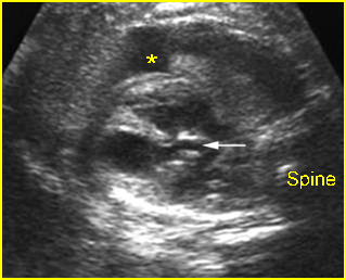
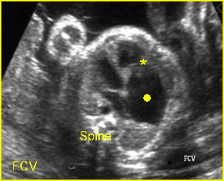
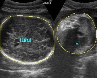
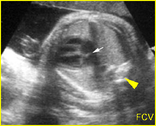
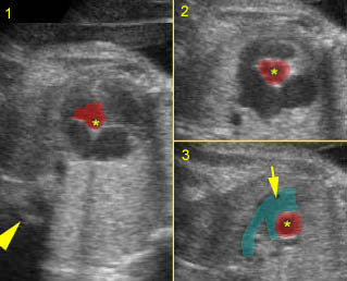
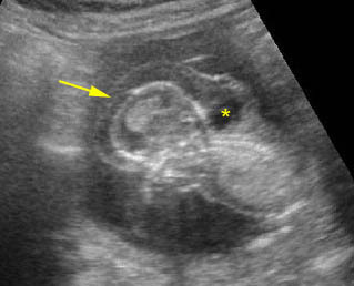
Cardiomegaly / Bradycardia:  Four-chamber view: generalized enlargement of the heart with pericardial effusion related to Hb Bart’s disease with bradycardia (arrowhead = spine)

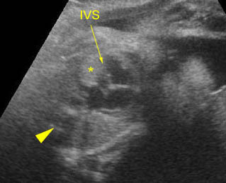
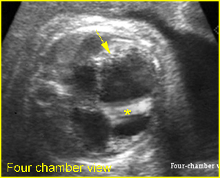
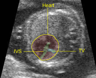
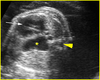
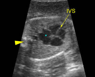
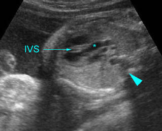
Cardiomyopathy :  Marked cardiomegaly with thickening of the interventricular septum (IVS)

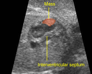
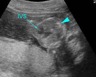
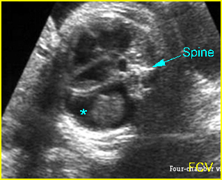
Cardiac rhabdomyoma:   Four-chamber view: echogenic mass (*) in the left ventricle (arrowhead = spine)

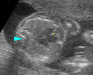
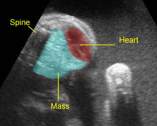
Small rhabdomyoma:  Small echogenic mass (5 mm) at the inner surface of the left ventricular wall

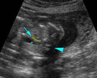
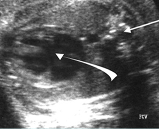
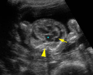
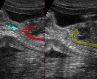
Coarctation of aorta:  Arch view at the upper thorax, extremely small aortic arch (arrow) compared to ductal arch (*) (arrowhead = spine)

Read More

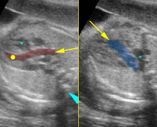
Abnormal Great Artery View

Abnormal Great Artery View

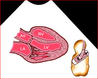
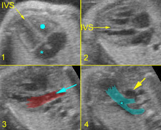
Example: Fig 1, Fig 2, Fig 3, Fig 4

Enlarged aortic root

  • Tetralogy of Fallot (most common)
  • Truncus arteriosus
  • Pulmonary atresia with ventricular septal defect

Small aortic root

  • Hypoplastic left ventricle (most common)
  • Coarctation or interruption of aorta

Small pulmonary artery

  • Pulmonary stenosis or atresia
  • Tetralogy of Fallot

Overiding aorta

  • Tetralogy of Fallot (most common)
  • Pulmonary atresia with ventricular septal defect
  • Truncus arteriosus
  • Double-outlet right ventricle

Parallel of the great arteries

  • Transposition of great arteries
  • Double-outlet right ventricle

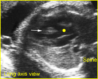
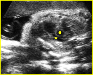
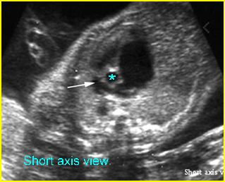
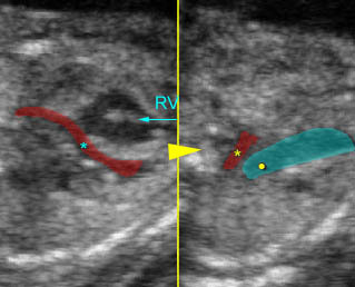
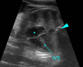
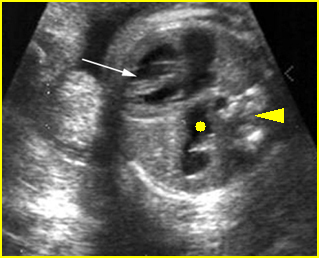
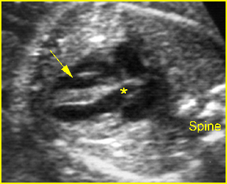
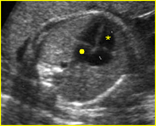
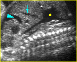
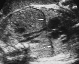
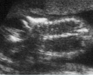
Fig 1:  Aortic stenosis  Long axis view: small aorta (arrow) (* = pleural effusion)

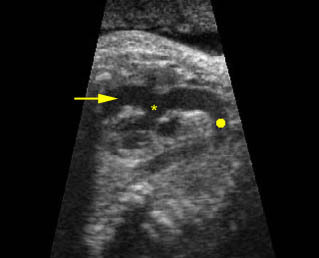
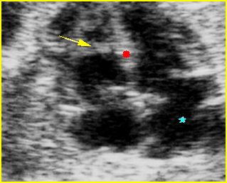
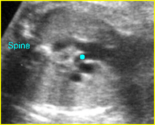
Fig 2:  Overriding aorta Long axis view: aortic root (solid circle) running from both ventricles (arrow = interventricular septum)

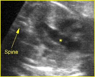
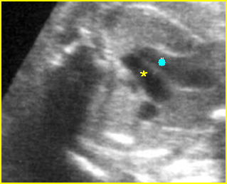
Fig 3:  Pulmonary stenosis (in case of TOF)  Long axis view of the heart: small pulmonary trunk (*) compared to aortic root (solid circle)

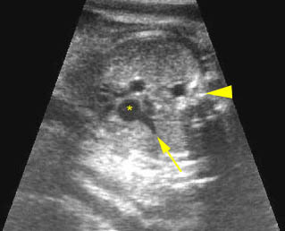
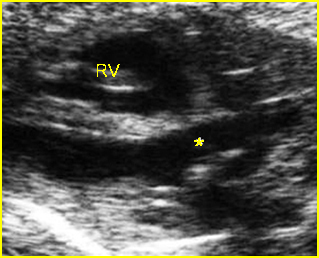
Fig 4:  Hypoplastic right heart syndrome   Short-axis view: small pulmonary trunk (arrow) compared to aorta (*) with large atrium

Video clips of abnormal great artery view

Hypoplastic left heart syndrome: 
– Long-axis view: small aortic root (*) arising from small left ventricle (arrowhead = spine)
– Arch view: small aortic arch (*), compared to large ductal arch (arrowhead = spine)

Double outlet of right ventricle :  
Long-axis view
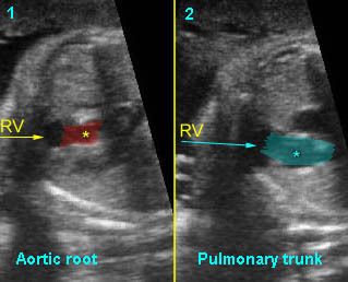
1) Aortic root arising from right ventricle
2) Pulmonary trunk arising from right ventricle

Coarctation of aorta: Arch view at the upper thorax, extremely small aortic arch (arrow) compared to ductal arch (*) (arrowhead = spine)

Overding aorta:  Longitudinal scan of the aoratic arch; * overiding aorta, solid circle = aortic arch, arrow = right ventricle

Truncus arteriosus:  Common trunk (aortic root) overiding both ventricles; small pulmonary artery (arrow) originating from the common trunk (*), (arrowhead =spine)

Read More

Abnormal Four-chamber View

Abnormal Four-Chamber View

Example: Fig 1, Fig 2, Fig 3, Fig 4

 Septal defects (see specific cardiac anomalies)

Left ventricle smaller than right ventricle

  • Artifacts: inappropriate plane
  • Early congestive heart failure
  • Hypoplastic left heart syndrome (HLHS); the most common structural defect of small left ventricle
  • Coarctation or hypoplastic arch
  • Double-outlet right ventricle

Right ventricle smaller than left ventricle

  • Artifacts: inappropriate plane
  • Triscuspid atresia (common)
  • Pulmonary atresia
  • Hypoplastic right heart syndrome (HRHS)

Enlarged right atrium

  • Tricuspid regurgitation or stenosis
  • Coarctation of aorta (also enlarged right ventricle)
  • Ebstein’s anomaly

Enlarged left atrium

  • Mitral stenosis
  • Severe mitral regurgitation

Abnormal cardiac axis (an abnormal axis increases the risk of a cardiac anomaly)

  • Normal variation
  • Pressure effect (intrathoracic mass)
  • Intrinsic cardiac anomaly (especially hypoplastic heart syndrome)

Fig 1:  Atrioventricular canal  Four-chamber view: common atrium and ventricle, no visible central crux (arrow)

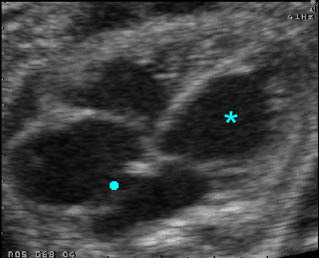
Fig 2:  Ebstein anomaly  Four-chamber view: enlarged atrium (solid circle) with low attachment of tricuspid valve (*)

Fig 3:  Atrioventricular canal  Four-chamber view: common atrium and ventricle, no visible central crux (arrow)

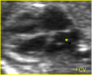
Fig 4:  Hyperthrophic cardiomyopathy  Four-chamber view: marked cardiomegaly, thickened interventricular septum (*) and echogenic endocardium (arrow)

Video clips of abnormal four-chamber view

Endocardial cushion defect:  Four-chamber view: atrial and ventricular septal defect, arrowhead = spine

Large ventricular septal defect:  Four-chamber view: incomplete interventricular septum (*), (arrowhead = spine)

Atrial septal defect:  Four-chamber view: abnormal cardiac axis, no atrial septum seen (arrowhead = spine)

Ebstein’s anomaly:  Ebstein’s anomaly in case of corrected transposition of the great artery: Low insertion of the tricuspid valve (TV) of the left-sided right ventricle (IVS = interventricular septum)

Cardiomyopathy:  Marked cardiomegaly with thickening of the interventricular septum (IVS) and poor contractility

Read More

Small Thorax

Small Thorax

            Fig 1, Fig 2

Pulmonary hypoplasia secondary to prolonged oligohydramnios remote from term is the most common cause, however, small thorax can be associated with several causes as follows:

  • Pulmonary hypoplasia
  • Skeletal dysplasia (such as thanatophoric dysplasia, osteogenesis imperfecta type II, short-rib polydactyly syndrome, Jeune’s syndrome, etc.)
  • Severe oligohydramnios secondary to preterm premature rupture of membranes or bilateral renal agenesis
  • Neurologic disorder (decreased breathing movements)
  • Bilateral lung agenesis (very rare)


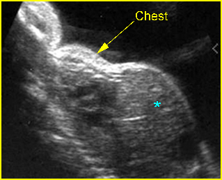
Fig 1:  Lung hypoplasia  Sagittal scan of the trunk: small thorax compared with abdomen (*) in association with chondroectodermal dysplasia

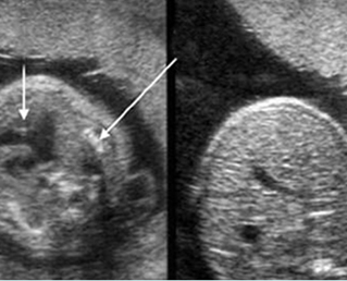
Fig 2:  Lung hypoplasia   Cross-sectional scan of the thorax and abdomen: small thorax with atrial septal defect (short arrow) and severely short rib (long arrow) in association with Jeune syndrome, compared to abdomen (right)

Video clips of small thorax

Lung hypoplasia / SRP Syndrome:  Small thorax (*) with short ribs compared to the head size in case of fetal short-rib polydactyly syndrome

Read More

Mediastinal Shift

Mediastinal Shift

            Fig 1, Fig 2

  • Unilateral or asymmetric pleural effusion
  • Chest masses secondary to any causes
  • Unilateral bronchial atresia
  • Unilateral agenesis of lung.

Fig 1:  Diaphragmatic hernia  Cross-sectional scan of thorax at the level of four-chamber view: cystic structure of bowel loop (*) located in the chest with cardiac displacement (arrow) to the right (arrowhead = spine)

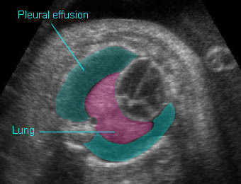
Fig 2:  Pleural effusion  Cross-sectional scan of thorax: pleural effusion (*) in the left thorax with cardiac displacement to the right

Video clips of chest masses

Diaphragmatic hernia:  Cross-sectional scan: The stomach is herniated into the chest with cardiac displacement

CCAM (Congenital cystic adenomatoid malformation: CCAM)
CCAM type III: Large echogenic lung mass with mediastinal shift

Read More

Pleural Effusion

Pleural Effusion

            Fig 1, Fig 2

Pleural effusion is one of the most common chest abnormalities; the most common cause of pleural effusion is hydrops fetalis secondary to various causes whereas it is due to isolated chylothorax in the minority of cases

  • Isolated primary chylothorax
  • Hydrops fetalis secondary to various causes
  • Chromosomal abnormalities, especially 45,XO, trisomy 21
  • Effusion associated mass, especially diaphragmatic hernia.

Fig 1:  Chylothorax  Oblique sagittal view of the fetus 21 weeks: pleural effusion (*)

Fig 2:  Pleural effusion  Cross-sectional scan of thorax: pleural effusion (*) in the left thorax with cardiac displacement to the right

Video clips of chest masses

Chylothorax:  Four-chamber view: marked pleural effusion (*) and subcutaneous edema (arrowhead), normal cardiac size

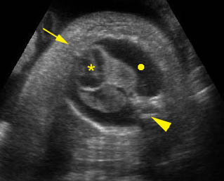
Hydrops fetalis:  Four-chamber view: marked pleural effusion (solid circle), normal cardiac size (*), subcutaneous edema (arrow) (arrowhead = spine)

Cardiomegaly / Pleural effusion:  Four-chamber view: markedly enlarged, occupying nearly total thoracic area, pleural effusion (arrow) (* = left atrium, arrowhead = spine)

Read More

Chest Masses

Chest Masses

A sonographic appearance of chest masses usually reveals the change in echogenicity (cystic, solid or mixed) and mediastinal shift. Sonographic characteristics of the masses can often help to narrow the diagnostic considerations. For example, nearly all chest masses are unilateral, and the bilateral solid masses are likely to be laryngeal or tracheal atresia. A completely solid mass may be a congenital cystic adenomatoid malformation (CCAM), sequestration, or obstructed lung. A solid and left lower lung mass has a high chance of being a pulmonary sequestration. A right lung solid-cystic mass is probably CCAM. A cystic mass with peristalsis is specific to a diaphragmatic hernia.

  Fig 1, Fig 2, Fig 3

The main differential diagnoses of chest masses are as follows:

Cystic

  • CDH (occasional peristalsis, absent stomach in the abdomen)
  • CCAM
  • Foregut duplication cyst (neurenteric, bronchogenic, enteric cyst)
  • Loculated fluid collection
  • Mediastinal meningocele

Cystic and Solid

  • CDH (occasional peristalsis, absent stomach in the abdomen)
  • CCAM
  • Foregut duplication cyst (neurenteric, bronchogenic, enteric cyst)
  • Teratoma (pericardial)

Solid

  • Sequestration (more common at lower lobe, vascular supply from aorta)
  • CDH (occasional peristalsis, absent stomach in the abdomen)
  • CCAM
  • Bronchial atresia
  • Bronchogenic with bronchial compression
  • Pericardial teratoma.

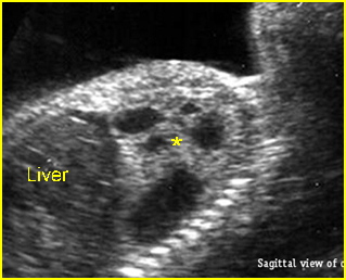
Fig 1:  Cystic adenomatoid malformation  Oblique sagittal scan of the fetal trunk: solid-cystic mass (*), mostly cystic, in the left chest (CCAM type I)

Fig 2:  Diaphragmatic hernia  Cross-sectional scan of thorax at the level of four-chamber view: cystic structure of bowel loop (solid circle) located in the chest with cardiac displacement to the right (arrowhead = spine)

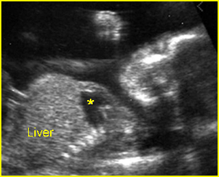
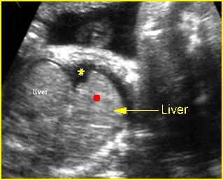
Fig 3:  Right diaphragmatic hernia   Sagittal scan of the chest: part of liver (solid circle) upward displacement to the chest (* = pleural effusion)

Video clips of chest masses

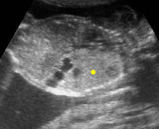
CCAM (Congenital cystic adenomatoid malformation: CCAM) Coronal scan of the chest: large echogenic mass (solid circle) in the left thorax with some cystic changes

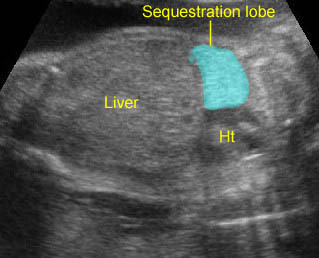
Lung sequestration:  Extralobar sequestration: Echogenic lung mass with lobar in shape

Diaphragmatic hernia:  Cross-sectional scan: The stomach is herniated into the chest with cardiac displacement

Read More

Normal Chest Examination (2)

Fetal Cardiac Examination

Congenital heart disease (CHD) is a leading cause of infant mortality with an estimated incidence of 4-8 per 1000 live births. Nonetheless, structural cardiac defects are among the most frequently missed abnormalities by prenatal ultrasound. Although currently prenatally diagnosed CHD is substantially improved, most cases world-wide are not prenatally diagnosed. The screening four-chamber view (FCV) may detect only 50-60% of cardiac anomalies and additional views of the outflow tracts will increase the sensitivity to 75%. The American Institute of Ultrasound in Medicine (AIUM) have introduced guidelines for cardiac screening, including examination of the four-chamber view and also outflow tracts. Furthermore, the level of operator experience is also an important factor that should be considered for fetal cardiac screening. Generally, fetal echocardiography is an extremely useful and accurate clinical tool for evaluation of a congenital heart with concordance of prenatal and postnatal echocardiography. When an abnormality is suspected, full fetal echocardiography should be performed. The scope of cardiac examination includes

  • basic cardiac examination: focus on the four-chamber view; this is the minimal requirement for standard examination
  • extended cardiac examination: including the outflow tracts; if technically feasible, this should be done on standard examination
  • full fetal echocardiography: complete cardiac examination which should be done as a specialized examination in suspected cases of CHD or pregnancies at risk, for example; intracardiac echogenic foci which increases the risk of Down’s syndrome five- to seven-fold.

Fig 1, Fig 2, Fig 3, Fig 4, Fig 5, Fig 6, Fig 7, Fig 8

Basic Cardiac Examination (FCV)

Fig 9, Fig 10, Fig 11, Fig 12

General considerations:

  • The examination can be performed optimally between 18 and 22 weeks of gestation.
  • Cardiac structures are often well visualized when the left ventricular apex is directed anteriorly toward the maternal abdominal wall, although there may be limitations secondary to improper fetal position, maternal obesity, and abdominal scar.
  • Chamber disproportion can sometimes be better appreciated when the interventricular and interatrial septae are perpendicular to the ultrasound beam.
  • Higher frequency transducers will improve the likelihood of detecting subtle defects but at the expense of reduced penetration.
  • A normal cardiac rate and regular rhythm should be confirmed. Heart rate typically ranges from 120 to 160 bpm.
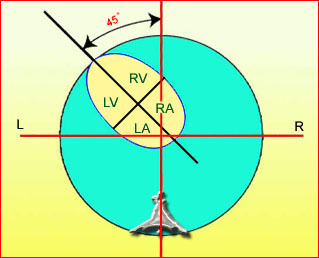
  • The heart axis is normally deviated about 45+20 (2 SD) degrees toward the left side of the fetus. An abnormal axis increases the risk of a cardiac malformation.
  • A normal small hypoechoic rim around the fetal heart can be mistaken for a pericardial effusion.
  • The basic screening examination entails a critical analysis of the FCV and outflow tracts. Correct analysis of the four-chamber view and both outflow tracts will exclude the majority of cases of serious congenital heart disease.

Technique: FCV

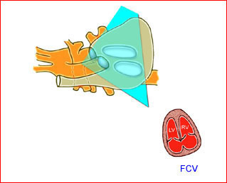
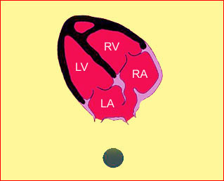
After determining the heart location within the left side of the chest, the same size<?should this be “side”? see below> as the stomach, the fetal thoracic spine is identified and then FCV is obtained from an axial plane across the fetal thorax. Anatomically, the right ventricle is behind the sternum, and the left ventricle is inferior and to the left of the right ventricle.

Checklist for Fetal Cardiac Screening Examination

General

  • Four cardiac chambers are present
  • The majority of the heart is located in the left chest, on the same size<?should this be “side”? see above> as the stomach
  • The heart occupies about one-third of the thoracic area
  • Normal cardiac situs, axis, and position
  • Heart beats regularly within normal limits for the fetal rate
  • No fluid accumulation is seen (pericardium, and pleural space)

Atria

  • Atria appear approximately equal in size
  • The foramen ovale flap moves within the left atrial chamber
  • The ostium primum attaches to the interventricular septum
  • The lower rim of atrial septum (septum primum) is present
  • Caval veins drain into the right atrium
  • Visualization of the pulmonary veins with B-mode ultrasound aided by color-flow Doppler can be accomplished in the majority of fetuses, while the four-chamber view is studied

Ventricles

  • Ventricles approximately equal in size, shape and wall thickness, without hypertrophy
  • Moderator band present at the right ventricular apex
  • Ventricular septum appears completely intact from apex to crux

AV Valves

  • Both atrioventricular valves are open and move freely
  • The septal insertion of the tricuspid valve is slightly lower than the mitral valve (normal off-setting of the atrioventricular valves).

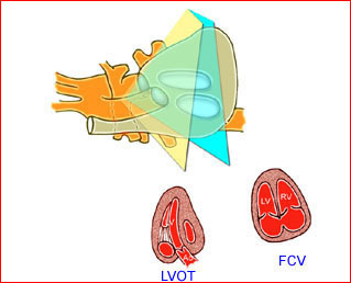
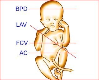
Fig 1:  Schematic drawing: The planes for four-chamber view (FCV) and long axis view (LAV) of the heart (BPD = biparietal diameter, AC = abdominal circumference)

Fig 2: Schematic drawing: Four-chamber view with typical cardiac axis, normal size and appropriate location (LA = left atrium, LV = left ventricle, RA = right atrium, RV = right ventricle)

Fig 3: Schematic drawing : The plane of the four-chamber view obtained from an axial scanning plane across the fetal thorax

Fig 4: Schematic drawing: Four-chamber view in relation to fetal spine; left atrium (LA) close to the spine and moderator band noted in the right ventricle (RV) (RA = right atrium, LV = left ventricle)

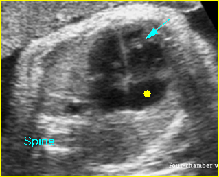
Fig 5: Normal four-chamber view  Cross-sectional scan of thorax: normal four-chamber view (arrow = moderator band in right ventricle, solid circle = right atrium)

Fig 6: Foramen ovale  Four-chamber view: normal four chambers (arrow = foramen ovale, arrowhead = spine)

Fig 7: Moderator band  Four-chamber view: normal four chambers, moderator band (arrow) in the right ventricle (* = left atrium)

Fig 8: Normal four-chamber view  Four-chamber view: normal four chambers, * = left atrium

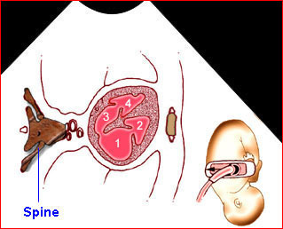
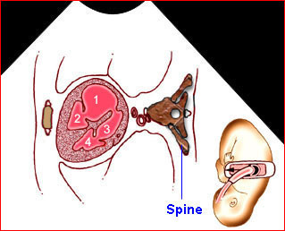
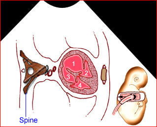
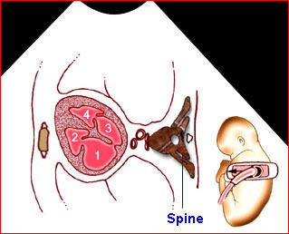
Fig 9: Schematic drawing: Four-chamber view in relation to fetal position (1 = right atrium, 2 = right ventricle, 3 = left atrium, 4 = left ventricle)

Fig 10:  Schematic drawing: Four-chamber view in relation to fetal position (1 = right atrium, 2 = right ventricle, 3 = left atrium, 4 = left ventricle)

Fig 11:  Schematic drawing: Four-chamber view in relation to fetal position (1 = right atrium, 2 = right ventricle, 3 = left atrium, 4 = left ventricle)

Fig 12:  Schematic drawing: Four-chamber view in relation to fetal position (1 = right atrium, 2 = right ventricle, 3 = left atrium, 4 = left ventricle)

Video clips of the normal heart

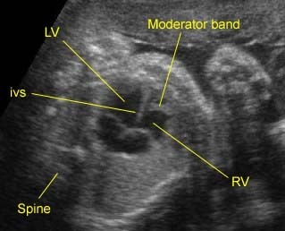
Normal four-chamber view: Typical four-chamber view: note the moderator band in the right ventricle (RV) (LV = left ventricle, IVS = interventricu-lar septum)

Normal four-chamber view:  Four-chamber view: * = left atrium, arrowhead = spine

Four-chamber view: Solid circle = foramen ovale, * = left ventricle, note the relationship between tricuspid and mitral valve insertion

Extended Basic Examination

If technically feasible, optional views of the outflow tracts can be obtained as part of an extended cardiac screening examination. Evaluation of outflow tracts can increase the detection rates for major cardiac malformations above that achievable by the FCV alone. This exam minimally requires that normal great vessels are approximately equal in size and that they cross each other at right angles from their origins as they exit from their respective ventricular chambers. Failure to confirm these criteria in a well-visualized study should alert the examiner that a more detailed evaluation may be warranted.

Fig 13, Fig 14, Fig 15, Fig 16, Fig 17, Fig 18, Fig 19

Technique: Outflow tract

The outflow tracts are typically obtained by angling the transducer toward the fetal head from a FCV when the interventricular septum is tangential to the ultrasound beam. A supplementary technique for evaluating the outflow tracts has also been described for the fetus when the interventricular septum is perpendicular to the ultrasound beam.

Left Ventricular Outflow Tract (LVOT)

Fig 20, Fig 21

The relation of the aortic root and left ventricle is best evaluated by the left ventricular long-axis view. This view is obtained by rotating the transducer from the FCV into a plane angled from the fetal stomach toward the right shoulder of the fetus. This plane is easiest obtained when the interventricular septum is perpendicular to the ultrasound beam in the FCV. This view may detect small ventricular septal defects and conotruncal abnormalities that are not seen on FCV. This view confirms the presence of a great vessel originating from the left ventricle. Continuity should be documented between the anterior aortic wall and ventricular septum. The aortic valve should be freely moving and not thickened.

When the LVOT is definitely the aorta, it may even be possible to trace the vessel into the arch from which three arteries originate into the neck.

Right Ventricular Outflow Tract (RVOT)

Fig 22, Fig 23

After examining the left ventricle and aortic outflow tract, tilt the transducer towards the anterior chest wall until the right outflow tract is imaged, which is perpendicular to the LVOT. Once this is accomplished, the main pulmonary artery is identified as it exits the right ventricle. It is slightly larger than the aortic root. The RVOT normally exits the right ventricle perpendicular to the more posteriorly positioned ascending aorta. The pulmonary outflow valve should be freely moving and not thickened. The RVOT can be confirmed as a pulmonary artery only if its distal end appears bifurcated. It divides toward the left side into the ductus arteriosus, which is contiguous with the descending aorta. The right side branches into the right pulmonary artery.

Summary

3 steps for outflow tract examination:

  • FCV: Once the FCV is identified, the ultrasound beam is directed perpendicular to the interventricular septum by sliding or rocking the probe at the maternal abdomen.
  • LVOT: After adjusting the FCV, the transducer is rotated approximately 45 degrees. In this position, the ultrasound beam is oriented in a diagonal plane from the fetal stomach toward the right shoulder.
  • RVOT: After imaging the LVOT, the transducer is kept in the same position and is then rocked, or tilted towards the anterior chest wall of the fetus to image the right outflow tract.

Out flow tract checklist

  • The ascending aorta and the main pulmonary artery are perpendicular to each other as they exit their respective ventricles.
  • The aortic and pulmonary valves are similar in size.
  • The outflow portion of the right ventricle merges with the main pulmonary artery. The pulmonary valve separates these two structures.
  • The main pulmonary artery bifurcates into the right and left pulmonary arteries.
  • The innominate, left common carotid, and/or the left subclavian arteries should be identified originating from the aortic arch.
  • The right pulmonary artery is inferior and perpendicular to the aortic arch.

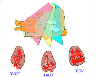
Fig 13:  Schematic drawing: The plane of the four-chamber view obtained from an axial scanning plane across the fetal thorax

Fig 14:  Schematic drawing: Left outflow tract view obtained by angling and slightly rotating the transducer from the four-chamber view toward the fetal head

Fig 15:  Schematic drawing: Right outflow tract view obtained by angling the transducer from the left outflow tract view toward the fetal head

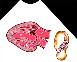
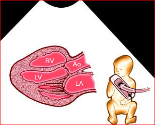
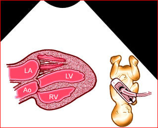
Fig 16:  Schematic drawing: Long-axis view in relation to fetal position (Ao = aortic root, LA = left atrium, LV = left ventricle, RV = right ventricle)

Fig 17:  Schematic drawing: Long-axis view in relation to fetal position (Ao = aortic root, LA = left atrium, LV = left ventricle, RV = right ventricle)

Fig 18:  Schematic drawing:Long-axis view in relation to fetal position (Ao = aortic root, LA = left atrium, LV = left ventricle, RV = right ventricle)

Fig 19:  Schematic drawing: Long-axis view in relation to fetal position (Ao = aortic root, LA = left atrium, LV = left ventricle, RV = right ventricle)

Fig 18:  Aortic root  Long axis view of the heart: normal aortic root (*) exiting the left ventricle (arrow = right ventricle)

Fig 21:  Aortic root  Long axis view of the heart: normal aortic root (*) exiting the left ventricle

Fig 22:  Normal great vessel view  Cross-sectional scan at the upper thorax: the relation of superior vena cava, ascending aorta, and pulmonary trunk in order (solid circle = right pulmonary artery arising from pulmonary trunk)

Fig 23:  Pulmonary trunk  Long axis view of the heart: normal pulmonary root (*) exiting the right ventricle

Fig 24:  Normal four-chamber view  Four-chamber view: normal four chambers, * = left atrium

Fig 25:  Aortic root  Long axis view of the heart: normal aortic root (*) exiting the left ventricle

Fig 26:  Normal great vessel view  Cross-sectional scan at the upper thorax: the relation of superior vena cava, ascending aorta, and pulmonary trunk in order (solid circle = right pulmonary artery arising from pulmonary trunk)

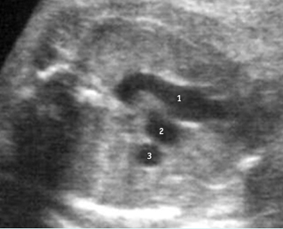
Fig 27:  Normal great vessel view  Cross-sectional scan at the upper thorax: the relation of superior vena cava (3), ascending aorta (2), and pulmonary trunk (1)

Fig 28:  Normal aortic arch  Cross-sectional scan of the upper thorax: aortic arch (*) and ductal arch (solid circle) running parallel to the descending aorta

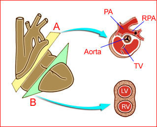
Fig 29:  Schematic drawing of the plane for short-axis view (PA = pul-monary trunk, RPA = right pulmonary artery, TV = tricuspid valve, LV = left ventricle, RV = right ventricle)

Video clips of the normal heart

Normal aortic root :  Long axis view: * = aortic root, arrowhead = spine

Long-axis view : 
1) aortic root arising from left ventricle (solid circle) (* = right ventricle)
2) pulmonary trunk arising from right ventricle, (* = ascending aorta)

Long-axis view : 
1) Four-chamber (solid circle = RV, *=LA)
2) Four-chamber view; IVS in horizontal plane
3) Ascending aorta
4) Pulmonary artery (*)

Great arteries: Sweeping 
1) Aortic root from left ventricle (arrowhead = spine)
2) Short axis view: * = aorta, (arrowhead = spine)
3) Pulmonary trunk (arrow), right pulmonary artery surrounding aorta (*)

Aortic & Ductal arch :
Longitudinal view of descending aorta:
1) aortic arch (arrow = carotid artery)
2) ductal arch (*)

Full Fetal Echocardiogram

A full fetal echocardiography includes multiple views of the heart:

  • Four chamber
  • Long-axis left ventricle
  • Short-axis great vessels
  • Pulmonary artery-ductus arteriosus
  • Aortic arch
  • Superior and inferior vena cava
  • Pulmonary veins

Additionally, color and spectral Doppler is used to identify small vessels such as the pulmonary veins and to assess valvular competence and flow patterns. Each of the views is obtained to provide specific information about the structure and/or function of the fetal heart. Inclusion of detailed fetal echocardiography as a screening examination has a substantial effect on the detection of congenital heart disease since a major proportion of prenatally detectable cases occur in a low-risk population. Attempts to perform full cardiac studies as part of routine second trimester fetal ultrasound have yielded high sensitivity rates, approximately 90% at 20-22 weeks, though fetal echocardiography can be successfully performed at 12-15 weeks of gestation permitting accurate early detection of major congenital heart defects in several cases of a high-risk population.

Tissue harmonic echocardiography seems to be the best technique to employ in obese women and in those in whom conventional ultrasound fails to provide diagnostic information. However, due its poorer resolution in women of average weight, conventional echocardiography should remain the technique of choice.

An abnormal cardiac finding during prenatal sonographic examination is a common primary indication for fetal echocardiography, accounting for 23.3% of examinations, and is more useful for identifying congenital heart disease than are other risk factors.

Increasing thickness of nuchal translucency at 11 and 14 weeks of gestation confers greater risk of congenital heart disease, even among euploid fetuses. Based on two meta-analyses, 30-56% sensitivity has been reported with a 5% false positive rate.

Use of Color-Flow Mapping and Pulsed Doppler

Routine use of color Doppler during every fetal cardiac examination remains controversial. Many examiners still believe that color should be reserved for cases of suspected congenital heart defect (CHD). Color-flow mapping is an important adjunct to cross-sectional scanning and can considerably speed up the cardiac evaluation. The correct direction of flow throughout the cardiac chambers and arch vessels can be demonstrated. It can be used to exclude regurgitation at any valve. At the usual Nyquist limits, unaliased color flow throughout the heart indicates that the flow is at normal velocities. If color shows aliasing at any point in the heart, pulsed Doppler should be used to obtain an accurate velocity. The peak velocity at the atrioventricular valves is 30-60 cm/sec and is fairly constant throughout gestation. The peak velocity of flow at the arterial valves is approximately 25 cm/sec at 12 weeks, increasing to 60-100 cm/sec by term. Turning on color flow when the ultrasound beam is perpendicular to the ventricular septum helps to exclude a significant ventricular septal defect. Color-flow mapping is essential to confirm a normal pulmonary venous connection. Routine use of pulsed Doppler is not necessary unless the color-flow map dictates it, but the fetal echocardiographer should be familiar with the characteristics of normal flow profiles at each point within the heart. The ultrasound beam must be positioned in-line with the flow under observation when using pulsed or color-flow mapping. This may require some technical skill. Color Doppler examination should include three cross-sectional planes: the four-chamber (4CV), five-chamber (5CV) and three-vessel (3VV) views.

Use of M-Mode Echocardiography

This modality is seldom used in fetal assessment and is not necessary during normal heart scanning. It can be used to assess ventricular function in the rare cases in which function is abnormal and it is useful in the evaluation of arrhythmias.

Three/Four-Dimensional Ultrasound

Three-dimensional imaging of fetal heart disease is feasible for a wide range of lesions, and may provide additional information of clinical value in some cases when compared with 2D imaging.

Read More

Normal Chest Examination

Normal Examination

Technique of examination

–     Transverse thoracic plane: Fig 1, Fig 2, Fig 3 The ultrasound transducer should be oriented to visualize the upper thorax first, from clavicles, and then move down to the abdomen. A sweep in transverse planes provides important information, including the ribs, thoracic spine, lung echogenicity, cardiac location, size, and axis. The four-chamber view can also be satisfactorily assessed. This view should be examined in all fetuses in the second and third trimesters as part of a routine scan. The thorax is rather round on this plane. The plane at the level of the four-chamber view can also perform thoracic circumference measurements.

–     Sagittal thoracic plane: Fig 4 The transducer should be adjusted to obtain the anteroposterior images from one side to the other. The thorax appears dome-shaped on this plane. The diaphragm and thoracic size compared with the abdomen can be assessed.

–     Coronal thoracic plane: Fig 5, Fig 6 The transducer is oriented to obtain the coronal images from the spine to the anterior wall. The thorax appears bell-shaped on this plane. The diaphragm and thoracic size compared with the abdomen can be assessed.

–     Bones assessment: Fig 7, Fig 8, Fig 9, Fig 10 The fetal thoracic cage is bell-shaped and bordered by the clavicles (which can also be measured) at the apices and the smooth hypoechoic diaphragm inferiorly. The ribs, smoothly marginated and regularly spaced, form the lateral boundaries and extend anteriorly and inferiorly more than halfway around the thorax from their dorsal attachments. The subjective impression of the thoracic size is sufficient in most cases. However, direct measurement of the thoracic circumference may be of value in the diagnosis of lung hypoplasia.

–     Lungs: Fig 11 The lungs have homogeneous mid-range echoes, however, the echogenicity may be greater than, less than, or equal to the echogenicity of the liver. The lungs may become progressively more echogenic than the liver as gestation progresses. No abdominal contents should be seen with the lungs.

–     Heart: Fig 2, Fig 3 On the transverse plane, the visualization of the normal four-chamber view of the heart with appropriate cardiac position, axis, and size helps to exclude many thoracic abnormalities. The four-chamber view examination can detect 60-70% of cardiac defects and an additional view of the ventricular outflow tracts and great vessels further increases that sensitivity. The heart occupies about one-third of the thoracic volume, and most of the cardiac volume is located in the left anterior quadrant of the chest. The cardiac axis, the angle that the interventricular septum makes with the line drawn from the spine to the anterior chest wall, ranges between 22 and 75 degrees, with a mean of 45 degrees. Echogenic foci caused by a specular reflection from the papillary muscles and chordae tendinae are commonly seen. The bright foci, termed echogenic intracardiac foci, can be associated with chromosome abnormalities.

–     Thymus: The thymus, a homogeneous, relatively hypoechoic structure in the anterior fetal mediastinum, could be visualized with some effort sonographically in 74% of 251 normal fetuses.

–     Larynx and Trachea: Fig11 The larynx is virtually always visible when the hypopharynx is fluid-filled. The fluid-filled trachea is a relatively easy structure to visualize. The fetus intermittently and frequently breathes amniotic fluid into the trachea. The trachea usually can be traced to its distal end, passing posterior to the aortic arch, but the carina and bronchi are quite difficult to perceive.
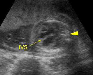
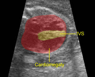
Fig 1:  Schematic drawing: Four-chamber view with typical cardiac axis, normal size and appropriate location (LA = left atrium, LV = left ventricle, RA = right atrium, RV = right ventricle)

Fig 2: Normal four-chamber view  Four-chamber view: normal four chambers; (* = right ventricle, solid circle = left atrium)

Fig 3: Normal four-chamber view  Cross-sectional scan of thorax: normal four-chamber view (arrow = moderator band in right ventricle, solid circle = right atrium)

Fig 4: Right atrium  Sagittal scan of the thorax: inferior vena cava and superior vena cava empty to the right atrium (solid circle) (* = diaphragm, arrow = umbilical vein, arrowhead = hepatic vein)

Fig 5: Intact diaphragm  Coronal scan of the trunk: normal diaphragm, hypoechoic line (arrow) above the liver

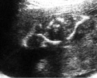
Fig 6: Scapula   Coronal view of thorax: normal triangular shape of the scapula

Fig 7: Normal capula  Coronal scan of the scapula: normal triangular shape

Fig 8: Clavicles  Cross-sectional scan of the upper thorax: normal clavicles

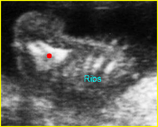
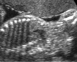
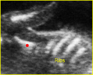
Fig 9: Ribs  Coronal scan of thorax: normal cross-section of the ribs with acoustic shadow

Fig 10: Scapula  Coronal view of normal triangular shape scapula (solid circle)

Fig 11: Normal four-chamber view  Four-chamber view: normal four chambers; (* = right ventricle, solid circle = left atrium)

Video clips of the normal heart

Normal four-chamber view: Typical four-chamber view: note the moderator band in the right ventricle (RV) (LV = left ventricle, IVS = interventricu-lar septum)

Pitfalls

  • False diagnosis of a diaphragmatic hernia: Oblique images of the chest and abdomen may include abdominal viscera in the heart. This may be misleading, causing the examiner to misinterpret normal findings as abnormal (i.e. false diagnosis of a diaphragmatic hernia).
  • Ribs in the abdomen: The ribs may extend inferiorly into the upper abdomen. Therefore, observation of the ribs and the abdominal structures in the same transverse plane should not be misinterpreted as abnormal.
  • Pseudo skin thickening: The thickening of subcutaneous tissue of the middle upper chest, including the scapula, may normally appear somewhat thicker than that of the abdomen or scalp.

Checklists

  • Normal heart location, axis and size
  • Normal thoracic size (compared with abdominal size)
  • No abnormal fluid collection or abnormal mass
  • Normal homogeneous echogenicity of lung
  • Normal ribs and thoracic spine.
Read More

Nuchal Translucency (NT)

Nuchal Translucency (NT)

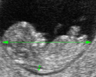
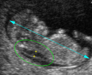
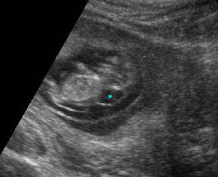
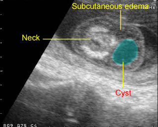
In the first trimester, the nuchal translucency (NT), instead of the nuchal fold, is used due to its sonographic appearance. NT normally increases with gestation and crown-rump length. It increases with crown-rump length and the median NT increases from 1.2 mm at 11 weeks to 1.9 mm at 13+6 weeks. Thickened NT may be due to fetal cardiac failure, abnormalities of the extracellular matrix, or abnormalities of the lymphatic system.

During the second trimester, NT usually resolves and in a few cases it evolves into either nuchal edema or cystic hygromas with or without hydropic changes. Extensive studies have now established that fetal NT, using the value of the 95th percentile for crown-rump length as a cut-off point, can effectively screen Down’s syndrome with a sensitivity of at least 75% for a false positive rate of <5%. In addition, the thickened NT is also associated with numerous syndromes (e.g. Cornelia de Lange, Noonan syndrome, Smith-Lemli-Opitz syndrome, Apert syndrome) or anomalies in euploid fetuses (e.g. major heart defects, diaphragmatic hernia) , and adverse outcome (early fetal demise) .

Sonographic measurement:

NT can be measured successfully by transabdominal ultrasound in about 95% of cases; in the other cases, it is necessary to perform transvaginal sonography. The average time allocated for each fetal scan should be at least 10 minutes. All sonographers performing fetal scans should be capable of reliably measuring the crown-rump length and obtaining a proper sagittal view of the fetal spine. It is essential that the same criteria are used to achieve uniformity of results among different operators:

  • The minimum fetal crown-rump length should be 45 mm and the maximum 84 mm. The optimal gestational age for measurement of fetal nuchal translucency is 11-13+6 weeks.
  • The results from transabdominal and transvaginal scanning are similar but the reproducibility may be better with the transvaginal method.
  • A good sagittal section of the fetus, as for measurement of crown-rump length, should be obtained.
  • The magnification should be such that the fetus occupies at least three-quarters of the image. Essentially, the magnification should be increased so that the increment in the distance between the calipers should be only 0.1 mm.
  • Care must be taken to distinguish between fetal skin and amnion because, at this gestation, both structures appear as thin membranes. This is achieved by waiting for spontaneous fetal movement away from the amniotic membrane; alternatively, the fetus is bounced off the amnion by asking the mother to cough and/or by tapping the maternal abdomen.
  • The maximum thickness of the subcutaneous translucency between the skin and the soft tissue overlying the cervical spine should be measured by placing the calipers on the lines as shown in Fig.<?which figure?>. During the scan, more than one measurement must be taken and the maximum one should be recorded.
  • The NT should be measured with the fetus in the neutral position. When the fetal neck is hyperextend the measurement can be increased by 0.6 mm and when the neck is flexed the measurement can be decreased by 0.4 mm.
  • The umbilical cord may be around the fetal neck in 5-10% of cases and this finding may produce a falsely increased nuchal translucency, adding about 0.8 mm to the measurement. In such cases, the measurements of NT above and below the cord are different and, in the calculation of risk, it is more appropriate to use the smaller measurement.

The ability to measure NT and obtain reproducible results improves with training; good results are achieved after 80 and 100 scans for the transabdominal and the transvaginal routes, respectively. Appropriate training, high motivation and adherence to a standard technique for the measurement of NT are essential prerequisites for good clinical practice.

In two large multicenter studies of first trimester Down’s syndrome screening, accurate nuchal translucency measurements required stringent training, formalized evaluation of sonographers’ competence, and continuing external quality control. In the latter trial, adequate NT images could not be obtained in 6% of cases.

Nuchal translucency:  Mid-sagittal scan of the fetus at 11 weeks of gestation showing NT and crown-rump length measurements

Thickened nuchal translucency:  Mid-sagittal scan of the fetus at 11 weeks of gestation showing the NT of 3.0 mm

Thickened nuchal translucency :  Sagittal scan of the fetus 10 weeks: cystic lesion (*) on the fetal neck

Early cystic hygroma :  Small non-septate cyst on the back of the neck with early hydrops fetalis (subcutaneous edema)

Early hydrops fetalis:  Sagittal scan of the fetus 13 weeks: generalized subcutaneous edema (arrow) with cystic fluid collection (on the back of the neck) (hydrops fetalis related to cystic hygroma)

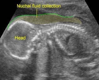
Markedly Thickened NT:  Nuchal fluid collection at the posterior aspect of the neck of the fetus with monosomy X

Read More